



Design Workflow
Discovery
Moodboard & Inspiration
Design 1 : Concept
High-Level Solution Formation
Design 2 : Plans
Low-Level Solution Formation
Development 1 : Modeling
Parametric Modeling
Development 2 : Manufacturing
Optimize Net & Assembly
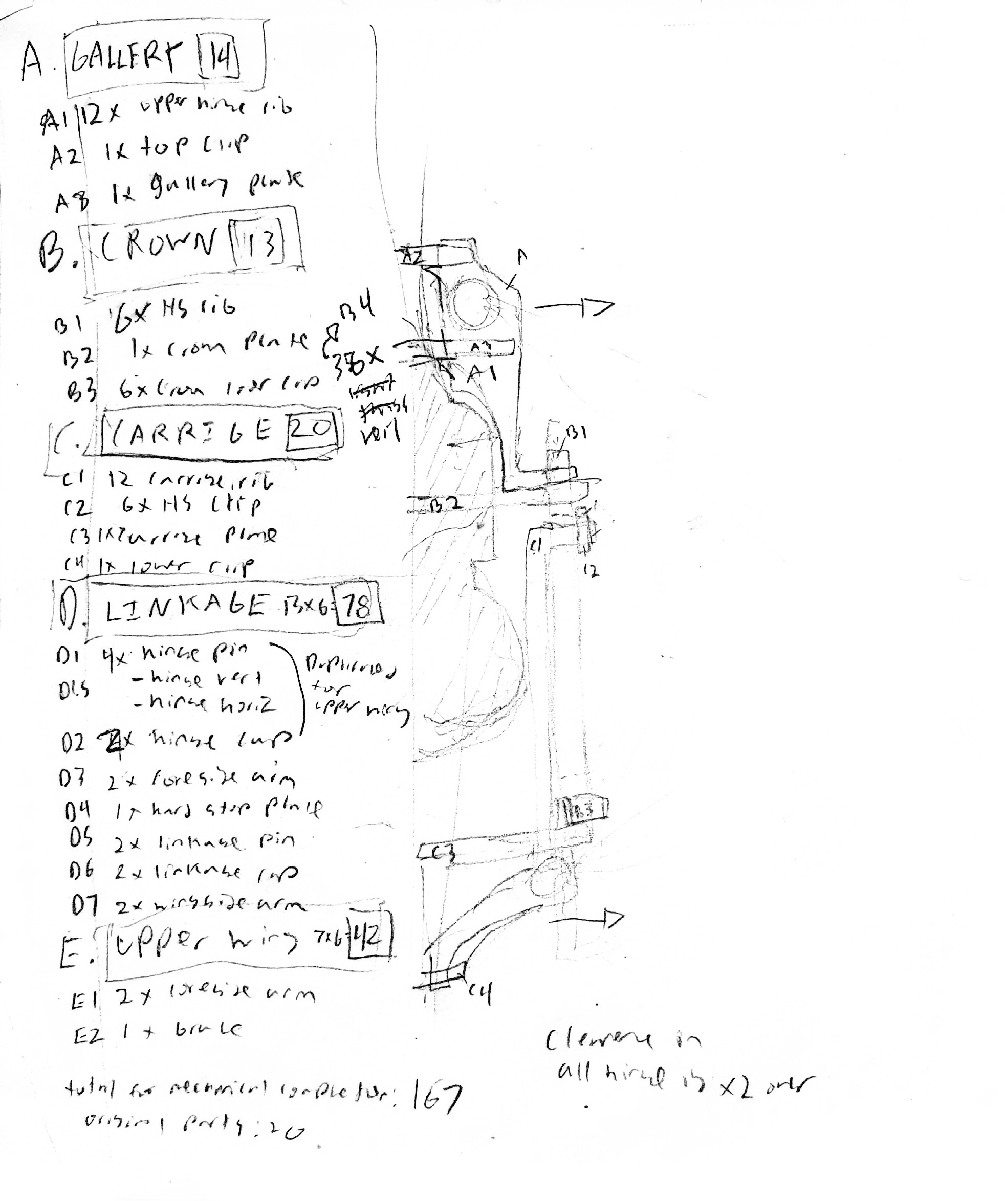
Sketches in background produced during design phase
Sketches in background produced during design phase
Understanding, Planning, and Vision
Design, for me, is about the intersection of understanding
and planning. And because I prioritized this dynamic, this
lamp assembled, functioned, and succeeded in two-thirds
the time and with half the material I was given. It was not
just my tools and my intuition, but because of the clarity I
had going through the process of what I needed to do.
Design, for me, is about the intersection of understanding
and planning. And because I prioritized this dynamic, this
lamp assembled, functioned, and succeeded in two-thirds
the time and with half the material I was given. It was not
just my tools and my intuition, but because of the clarity I
had going through the process of what I needed to do.

Fully Closed
Fully Closed

Partially Open
Partially Open

Locked Open
Locked Open
Product Description
Opera is a posable lamp made purely out of laser cut MDF. It consists of a movable shade, which is operated by pulling a carriage towards or away from the lightbulb.
Opera is a posable lamp made purely out of laser cut MDF. It consists of a movable shade, which is operated by pulling a carriage towards or away from the lightbulb.
In the closed state, all wings lie close to the bulb, shielding it's light. In it's open state, the wings are open, exposing the bulb. They lock using an over-center linkage.
In the closed state, all wings lie close to the bulb, shielding it's light. In it's open state, the wings are open, exposing the bulb. They lock using an over-center linkage.
Requirements
Requirements
Direction: Serial Patterns
Stock: 2x 16x24in 3mm MDF. LED lightbulb provided.
Timeline: 2.5 Weeks
Direction: Serial Patterns
Stock: 2x 16x24in 3mm MDF. LED lightbulb provided.
Timeline: 2.5 Weeks
Create a beautiful, sculptural lamp meant to serve as a display piece. MDF only. Laser cutter only. No adhesives or other fasteners. No tools for assembly. Flat-packable.
Create a beautiful, sculptural lamp meant to serve as a display piece. MDF only. Laser cutter only. No adhesives or other fasteners. No tools for assembly. Flat-packable.
DISCOVERY
DISCOVERY
The underlying aesthetic point of truth emerged from the examination of three fields: serial patterns in nature, architectural bowelism, and the machine aesthetic.
HEY!
This project page looks WAY COOLER on a bigger screen!
Moodboard
The underlying aesthetic point of truth emerged from the examination of three fields: serial patterns in nature, architectural bowelism, and the machine aesthetic. The
… See More


Moodboard
The underlying aesthetic point of truth emerged from the examination of three fields: serial patterns in nature, architectural bowelism, and the machine aesthetic. The compelling complexity of artificial and organic radial seriality, I argue, emerges in part through fundamentally symmetrical forces, such as gravity and fluid movement. Thus, the shape of my lamp will similarly embrace the symmetrical influence of light. Bowelism returns to the Gothic ideal of exposing structural components as aesthetic form and pushing them to the outside, maximizing the interior volume as well as the permeation of light. My lamp will follow the same concept by adopting a mechanical manifold, opening and closing, with the revealed mechanism as aesthetic vessel.


Dragonfly - Downwards Facing Wings
Dragonfly - Downwards Facing Wings

Pinflower - Rotating Cams
Pinflower - Rotating Cams

Sungazer - Upwards Facing Wings
Sungazer - Upwards Facing Wings
The illustrations served a purely exploratory purpose in terms of investigating proportions, with only the bare minimum of thought put towards mechanical feasibility. The eye and taste of an artist was needed to select the best idea- the one that most closely embodied the atmosphere of the mood board.
The illustrations served a purely exploratory purpose in terms of investigating proportions, with only the bare minimum of thought put towards mechanical feasibility. The eye and taste of an artist was needed to select the best idea- the one that most closely embodied the atmosphere of the mood board.
The ‘Dragonfly’ design was chosen after group critique.
The ‘Dragonfly’ design was chosen after group critique.
CONCEPT
CONCEPT
Mechanical Objectives, Constraints, and aesthetic goals form the necessary subsystems and their singular points of truth.

Mechanical Functions
The wings fold up and down
The wings resist gravity in the up position
The user manipulates the wing positions
The wings fold up and down
The wings resist gravity in the up position
The user manipulates the wing positions
Overall Goals
There are as few components as possible
The lamp maximizes the material of the sheet
The structure is stiff enough to maintain shape
There are as few components as possible
The lamp maximizes the material of the sheet
The structure is stiff enough to maintain shape
Developing the Subsystems
Clearly, at least three subsystems were necessary. The wing, which moves, a core, which attaches the lamp to the bulb, and a linkage, which locks the wing into place. The core can further be subdivided- an element of the core must be able to move, which the user interacts with, requiring another subsystem to constrain the moving component as well as constraining the wing to the bulb.
Clearly, at least three subsystems were necessary. The wing, which moves, a core, which attaches the lamp to the bulb, and a linkage, which locks the wing into place. The core can further be subdivided- an element of the core must be able to move, which the user interacts with, requiring another subsystem to constrain the moving component as well as constraining the wing to the bulb.
This brings to total to four subsystems: Fixed core, moving core, wings, and linkages.
Now that I knew what I needed, I gave them all silly names mirroring what I envisioned in my head- and wrote the singular points of truth that would drive the rest of the design process, arriving at my vivid concept.
Now that I knew what I needed, I gave them all silly names mirroring what I envisioned in my head- and wrote the singular points of truth that would drive the rest of the design process, arriving at my vivid concept.
The Gallery is the hinge for the wings. It rests upon the Crown.
The Gallery is the hinge for the wings. It rests upon the Crown.
The Crown is fixed relative to the bulb. It serves as the hard stop for the Carriage.
The Crown is fixed relative to the bulb. It serves as the hard stop for the Carriage.
The Carriage is moved by the user and constrained by the Linkage & Crown.
The Carriage is moved by the user and constrained by the Linkage & Crown.
The Linkage connects the Carriage to the Wing and locks over center.
The Linkage connects the Carriage to the Wing and locks over center.
PLANS
PLANS
Interpretation of the vivid concept through DFMA and mechanical intuition produces a complete list of parts and their functions.
The Night of the Numbers
In this process, I needed to visualize the construction and assembly of every single component in order to count it, focusing on interactions with other components and the final geometry. Every part needed to complete its assigned function as well as conform to the design constraints.
Mentally, once I had a list of all parts, I could reduce part count while still staying mentally conscious on how these changes would affect the entire subsystem. The main question I asked myself: How does it serve the subsystem’s singular point of truth? If a part was not serving a point of truth, then it could be removed.
The Night of the Numbers
In this process, I needed to visualize the construction and assembly of every single component in order to count it, focusing on interactions with other components and the final
… See More

What is Timothy Thinking?
For example, to create rotating joints, I broke down the problem into simpler parts.
For example, to create rotating joints, I broke down the problem into simpler parts.
I needed to constrain an axle, and constrain some sort of arm extending from the axle. For an axle to spin, it needed to be in a round housing. No problem, the laser can cut round holes into sheet.
The axle itself can just be a single sheet, since it has noticeable thickness of 3mm, but for best results we need the best approximation of a circular profile made with intersecting planes- a cross shape.

The axle needs to not fall out of the housing, so it can be constrained by a press-fit clip at one end, and the axle geometry can constrain it from falling out the other end.


The output arm can be constrained between the two housing plates, but if more than one output arm is required, they need to be further constrained from moving too close to each other, which can be done by altering axle geometry.
Which axle plane should I add this element in? Clearly not the one already keeping the axle from falling out of the housing, then assembly would be impossible! After this is done, the universal laser cut hinge is completed.


I needed to constrain an axle, and constrain some sort of arm extending from the axle. For an axle to spin, it needed to be in a round housing. No problem, the laser can cut round holes into
… See More


The axle needs to not fall out of the housing, so it can be constrained by a press-fit clip at one end, and the axle geometry can constrain it from falling out the other end.
… See More


The output arm can be constrained between the two housing plates, but if more than one output arm is required, they need to be further constrained from moving too close to each other,
… See More
After a brief design review it seems mechanically feasible and feasible to manufacture, as well as possible to assemble. So overall, a sturdy hinge requires 2x housing pieces, 2x axle pieces, 1 press fit clip, 2x output arms.
After a brief design review it seems mechanically feasible and feasible to manufacture, as well as possible to assemble. So overall, a sturdy hinge requires 2x housing pieces, 2x axle pieces, 1 press fit clip, 2x output arms.
Repeat for every other part.
MODELING
MODELING
Taking advantage of parametric CAD to design a responsive, flexible model that could be edited to fit manufacturing tolerances.
Global Variables
My digital input needed to be as flexible and responsive as possible if I wanted my lamp to come together first try. For this application, equation driven parametric modeling in SolidWorks was the clear answer. This way, through changing a single variable, I could adjust press and slip fit tolerances responsively across the entire model. With a project with so many mechanical components, this was necessary. Otherwise, changing a variable manually across hundreds of sketches would REALLY SUCK! I prefer to suffer meaningfully!
Global Variables
My digital input needed to be as flexible and responsive as possible if I wanted my lamp to come together first try. For this application, equation driven parametric modeling in
… See More
Master Sketching
Master Sketching is a top-down design paradigm that uses a skeleton framework that is converted into and drives multiple bodies- taking full advantage of the parametric capabilities of SolidWorks to reflexively adjust the model without needing to edit each body individually. For example, if I wanted to change the maximum splay angle, instead of having to remodel the entire linkage, I could change a single dimension in the master sketch and the necessary changes propagates automatically throughout the dozen or so parts.
Master Sketching
Master Sketching is a top-down design paradigm that uses a skeleton framework that is converted into and drives multiple bodies- taking full advantage of the parametric
… See More


Test Cuts
I conducted some preliminary laser cuts to determine some reasonable baseline inputs for my equations, focusing on the three types of joints that drove the design most significantly: Axle-housing, 3-walled slots, and 4-walled slots (clips). After arriving at the tolerance numbers for the specific laser cutter and material, I could begin to CAD in earnest.
Test Cuts
I conducted some preliminary laser cuts to determine some reasonable baseline inputs for my equations, focusing on the three types of joints that drove the design most
… See More

Final Mechanism
This style of system-oriented design forced me to seriously consider every entity that I created, tying everything back as purely as possible to the objectives and constraints that I first established I had determined at the beginning of the project. The symmetrical influence of light. Revealed mechanism as aesthetic medium.
This style of system-oriented design forced me to seriously consider every entity that I created, tying everything back as purely as possible to the objectives and constraints that I first established I had determined at the beginning of the project. The symmetrical influence of light. Revealed mechanism as aesthetic medium.
After my global variables were set up, my master sketch was completed, my catalogue of parts and universal points of truth were established, developing the model was very straightforward. Everything was where it needed to be- I followed procedure and it all simply fell into place.
After my global variables were set up, my master sketch was completed, my catalogue of parts and universal points of truth were established, developing the model was very straightforward. Everything was where it needed to be- I followed procedure and it all simply fell into place.
The Gallery is the hinge for the wings. It rests upon the Crown.
The Gallery is the hinge for the wings. It rests upon the Crown.
The Crown is fixed relative to the bulb. It serves as the hard stop for the Carriage.
The Crown is fixed relative to the bulb. It serves as the hard stop for the Carriage.
The Carriage is moved by the user and constrained by the Linkage & Crown.
The Carriage is moved by the user and constrained by the Linkage & Crown.
The Linkage connects the Carriage to the Wing and locks over center.
The Linkage connects the Carriage to the Wing and locks over center.
The Wing articulates to conceal or reveal the bulb.
The Wing articulates to conceal or reveal the bulb.


MANUFACTURING
MANUFACTURING
Optimizing the nesting and placement of components to expedite organization and assembly, as well as a perfect fit.

After the manufacturing stock was selected, I updated the model with the exact dimension and tolerances of this particular piece of stock on this particular machine, to ensure an absolutely optimized fit.
Upon reflection this might have been a little bit overkill, but it nonetheless allowed the lamp to be assembled on the first iteration without any issues and integrated flexibility to be adjusted easily in the future for varying stock thicknesses and tolerances.

After the manufacturing stock was selected, I updated the model with the exact dimension and tolerances of this particular piece of stock on this particular machine, to ensure an absolutely optimized fit.
Upon reflection this might have been a little bit overkill, but it nonetheless allowed the lamp to be assembled on the first iteration without any issues and integrated flexibility to be adjusted easily in the future for varying stock thicknesses and tolerances.


Orginization
Although as the creator I understand every component intimately, in the future if I was to commercially produce this lamp I would probably edit the cut file so that the components are grouped by subsystem, so the parts would optimally be pre-organized out of the laser.


