HEY!
This project page looks WAY COOLER on a bigger screen!
Context: What is ARC?
ARC was formerly affiliated with DJI’s RoboMaster combat robotics competition. In our game, robots launch physical projectiles to strike pressure sensors mounted on opposing robots, depleting virtual health and eventually shutting them down. The competition demands robust physical platforms for both consistently dealing and resisting damage while having strong mobility to outmaneuver enemies.
The Sentry archetype is very unique in that it lacks a human driver- it traverses the field, engages enemies, and makes strategic decisions purely autonomously.
ARC was formerly affiliated with DJI’s RoboMaster combat robotics competition. In our game, robots launch physical projectiles to strike pressure sensors mounted on opposing robots, depleting virtual health and eventually shutting them down. The competition demands robust physical platforms for both consistently dealing and resisting damage while having strong mobility to outmaneuver enemies.
The Sentry archetype is very unique in that it lacks a human driver- it traverses the field, engages enemies, and makes strategic decisions purely autonomously.

Basic Specs:
Weight: 19kg
Size: 585mm Dia.
Translational Speed: 2.5 m/s
Power Limit: 30 V
Magazine Capacity: 765
Fire Rate: 25 - 30 Hz
Cost (w.o. labor): ~$9,000
Comp Results: 3rd Place Overall, 2nd USA
The unconventional double yaw architecture of Achyls - a design optimized for sensor stability and control authority- is the legacy of four years of constant innovation. Improvements made to the general architecture by relocating the bearing underneath the major structure, allowing firing system and electronics to sit on top of the chassis instead of being encased inside, improves packaging, weight, and stability characteristics.
The unconventional double yaw architecture of Achyls - a design optimized for sensor stability and control authority- is the legacy of four years of constant innovation. Improvements made to the general architecture by relocating the bearing underneath the major structure, allowing firing system and electronics to sit on top of the chassis instead of being encased inside, improves packaging, weight, and stability characteristics.
DESIGN PROCESS
DESIGN PROCESS
Top Down Design Philosophy
Design Failures & Learnings
Case Study: Yaw Mech Subsystem
Top Down Design
Let’s figure it all out now, plan everything so it can’t get us later.
Top Down Design
Let’s figure it all out now, plan everything so it can’t get us later.
Bottom Up Design
There is no way to figure it all out- we need to do it as we go.
Bottom Up Design
There is no way to figure it all out- we need to do it as we go.


Master Sketching & Top Down
A single master sketch holds all of the key driving relations throughout all of yaw mech and chassis. For example- in the past, shifting a single component creates a terrible cascade downsteam-every part near it needed to have dimensions altered resulting in dozens of changes and potential risks. With mastersketching, since everything is tied to a singular point of truth, all of the changes are automatic.
Parametric CAD is less like sculpting and more like programming with geometry in order to get a desired output. CAD tools are secretly programming languages wearing a 3-D modeling costume.
Master Sketching & Top Down
A single master sketch holds all of the key driving relations throughout all of yaw mech and chassis. For example- in the past, shifting a single component creates a terrible
… See More
Design for Manufacturing & Assembly
When designing a machine this complex, the design process must be especially rigorous. The story of every fastener & component needs to be considered from start to finish- how is it installed? Is it accessible for visual inspection and retightening? How does it impact its friends? What is it constrained by? What does it constrain? How does this impact the robot as a whole? This process must be done for every edge, hole, and surface. Tedious? Yes. Essential? Certainly.
Design for Manufacturing & Assembly
When designing a machine this complex, the design process must be especially rigorous. The story of every fastener & component needs to be considered from start to finish-
… See More
Design Flaws We Encountered
Over Integration of Systems
In order to save weight, many of our systems are so closely integrated that they are difficult to separate from each other for individual repairs. The best example is how the entire chassis sandwich needs to be deconstructed to repair or replace any individual component since it is all being held together by the same screws. Like how replacing the tomato out of a big burger requires taking the toothpick out. It SUCKED!
Exclusionary nature of Top Down
Undesigned changes rips throughout the entire system automatically, causing problems to arise that are difficult to diagnose. In order to fully harness top down, every element of uncertainty needs to be banished from the very beginning- the system itself is tremendously cohesive and efficient but lacks the decentralized flexibility of bottom up.
Design Flaws We Encountered
Over Integration of Systems & the
Exclusionary nature of Top Down
Undesigned changes rips throughout the entire system automatically, causing problems to arise that are difficult to diagnose. In order to fully harness top down, every element .
… See More
Iteration
This robot was developed on an extremely accelerated schedule, and as such, a lot of new information was actively being revealed through R&D and many decisions were actively being made alongside the design process. This resulted in the robot undergoing major changes through almost every subsystem. Let’s focus on my personal subsystem, which had to be completely reworked four times:
This robot was developed on an extremely accelerated schedule, and as such, a lot of new information was actively being revealed through R&D and many decisions were actively being made alongside the design process. This resulted in the robot undergoing major changes through almost every subsystem. Let’s focus on my personal subsystem, which had to be completely reworked four times:
1: On Axis Encoder 1:1 Under Major Stack
Optimization: Packaging
Initial Yaw Mech design derived from proven legacy designs. The custom on-axis absolute encoder requires a 1:1 pulley ratio. Optimized for as small a package as possible, using the motor as the defining vertical constraint in the chassis.
Initial Yaw Mech design derived from proven legacy designs. The custom on-axis absolute encoder requires a 1:1 pulley ratio. Optimized for as small a package as possible, using the motor as the defining vertical constraint in the chassis.
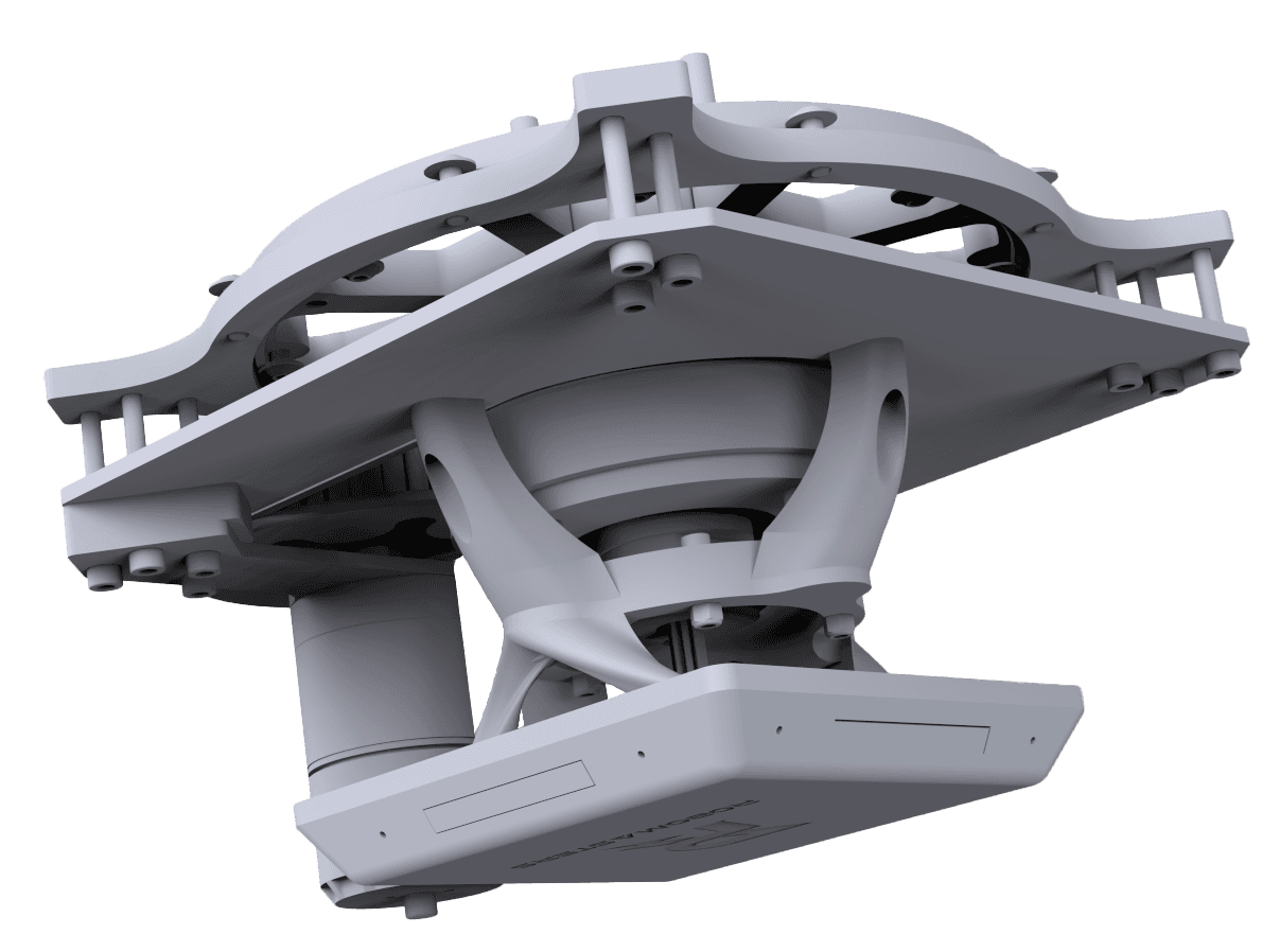
Strategy team requests our robot to be as short as possible.
2: On Axis Encoder 1:1 Out Of Major Stack
Optimization: Height
By kicking the motor out of the footprint of major and mounting it upside down, the on-axis encoder chip becomes instantly much more accessible and the chassis size can be aggressively compressed to the height of the slipring. However, the elegant packaging of the intentional design is lost as yaw mech is completely integrated into chassis.
By kicking the motor out of the footprint of major and mounting it upside down, the on-axis encoder chip becomes instantly much more accessible and the chassis size can be aggressively compressed to the height of the slipring. However, the elegant packaging of the intentional design is lost as yaw mech is completely integrated into chassis.
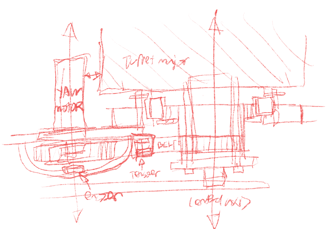

Software team requests higher precision telemetry.
3: Backlash Optimized Lamprey
Optimization: Backlash Reduction
By ditching the on-axis encoder and using a through-bore absolute encoder, a non 1:1 pulley ratio becomes possible. The backlash from the motor gearbox becomes diluted by the pulley ratio, improving telemetry.
By ditching the on-axis encoder and using a through-bore absolute encoder, a non 1:1 pulley ratio becomes possible. The backlash from the motor gearbox becomes diluted by the pulley ratio, improving telemetry.


Software team requests integration of an on-axis encoder to get accurate absolute positioning.
4: On Axis + Lamprey Design Retrofit
Optimization: Percision
After installation, it was discovered that the through-bore encoder that we got (which was a budget encoder) really SUCKED! An emergency retrofit was required of the on-axis encoder into the final design.
After installation, it was discovered that the through-bore encoder that we got (which was a budget encoder) really SUCKED! An emergency retrofit was required of the on-axis encoder into the final design.


Although constantly reworking the robot was frustrating, the result is a truly optimized architecture, every decision considered and reconsidered multiple times.
MANUFACTURING
MANUFACTURING
Methods & Materials
Assembly
Case Study: Armor & Battery Cover


Metal Machining
6061 aluminum is the material of choice for many structural components. The major benefit over Carbon Fiber is ease of manufacture and the ability to be tapped into.
Metal Machining
6061 aluminum is the material of choice for many structural components. The major benefit over Carbon Fiber is ease of manufacture and the ability to be tapped into.
… See More
Yaw Hub Clamp:
This was perhaps the most cathartic part I have designed and manufactured, because it was my final ultimatum to an issue with last year’s robot that caused me a lot of stress and frustration. By making the clamping symmetrical, hub slipping is now a relic of the past.
This was perhaps the most cathartic part I have designed and manufactured, because it was my final ultimatum to an issue with last year’s robot that caused me a lot of stress and frustration. By making the clamping symmetrical, hub slipping is now a relic of the past.


3D Printing
With 3D printing, conventionally impossible geometry becomes very accessible to manufacture and implement- allowing my imagination to run wild. Due to it's low weight and easy manufactuability, it also is a great material to make small components out of. 3D printed parts consist of a large portion of our robot.
… See More
3D Printing
With 3D printing, conventionally impossible geometry becomes very accessible to manufacture and implement- allowing my imagination to run wild. Due to it's low weight and easy manufactuability, it also is a great material to make small components out of. 3D printed parts consist of a large portion of our robot.
Armor Panel Mounts
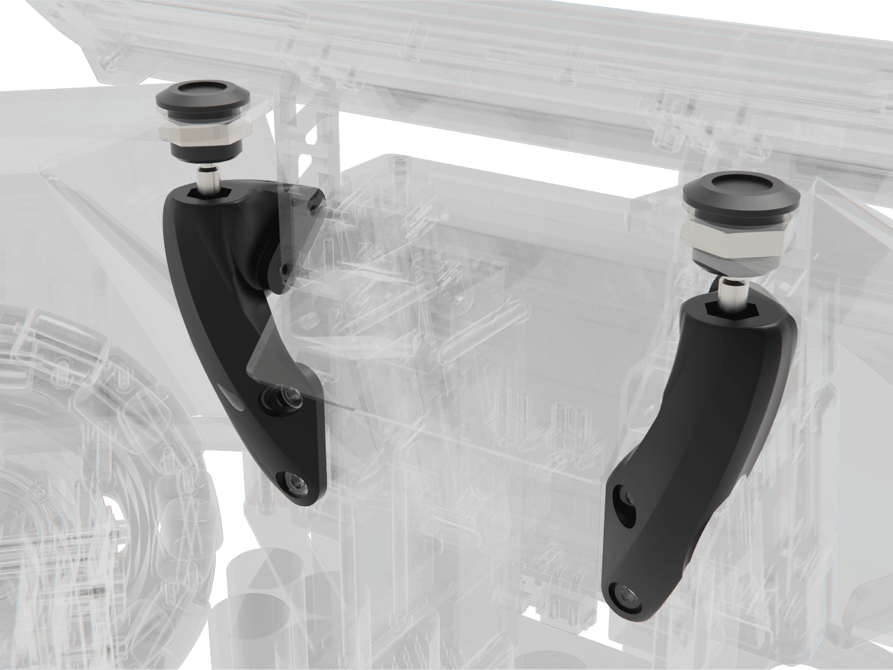
These mounts are designed to mount our armor panels to an unconventional location. As an industrial designer, I have a lot of fun creating surfaced parts and these were a particular treat due to the challenging mounting.
These mounts are designed to mount our armor panels to an unconventional location. As an industrial designer, I have a lot of fun creating surfaced parts and these were a particular treat due to the challenging mounting.



Carbon Fiber
Composite materials are lightweight yet rigid- making them key components for large structural sheets as a replacement for aluminum. Laying up carbon and having it bake in the platen press required a lot of staying up late and babysitting sheets, but in the end, it was a lot of fun!
… See More
Carbon Fiber
Composite materials are lightweight yet rigid- making them key components for large structural sheets as a replacement for aluminum. Laying up carbon and having it bake in the platen press required a lot of staying up late and babysitting sheets, but in the end, it was a lot of fun!


ABS
Bent ABS sheets form the armor of the robot-my domain. Aside from directly contributing to the battle readiness of our robots, the armor of our robots feeds directly into the visual identity of the machine.
… See More
ABS
Bent ABS sheets form the armor of the robot-my domain. Aside from directly contributing to the battle readiness of our robots, the armor of our robots feeds directly into the visual identity of the machine.
Battery Cover+Metafoam
A combination of bent plastic and TPU infill as a hybrid gives the battery cover incredible damage resilience even with very limited space, surviving multiple direct heavy hits during competition.
A combination of bent plastic and TPU infill as a hybrid gives the battery cover incredible damage resilience even with very limited space, surviving multiple direct heavy hits during competition.


In depth Study: Developing armor panels
Designing armor for this robot was more difficult than usual. Due to the chassis layout, all of the mounting points were not only unsymmetrical but lopsided slightly in every direction. This was extremely frustrating! Coming up with a way to make this robot look good seemed impossible.
Designing armor for this robot was more difficult than usual. Due to the chassis layout, all of the mounting points were not only unsymmetrical but lopsided slightly in every direction. This was extremely frustrating! Coming up with a way to make this robot look good seemed impossible.
First iteration: Design around mounting holes
The first concepts were the ‘engineer solution’, trying to fit some sort of covering over the electronics at any cost, building the covers around the asymmetrical mounting points and hoping for the best. For a round robot, all of these designs were technically acceptable but decidedly ugly.
The first concepts were the ‘engineer solution’, trying to fit some sort of covering over the electronics at any cost, building the covers around the asymmetrical mounting points and hoping for the best. For a round robot, all of these designs were technically acceptable but decidedly ugly.


Quick Concept Sketches
I printed out the mounting situation and directly sketched onto it and thus was able to quickly produce some basic concepts about faceting and chunk out the form. After I became a bit more comfortable and had some good ideas, I brought it into CAD and used 3-D sketches to quickly prototype a few more ideas, checking against clearance zones.
I printed out the mounting situation and directly sketched onto it and thus was able to quickly produce some basic concepts about faceting and chunk out the form. After I became a bit more comfortable and had some good ideas, I brought it into CAD and used 3-D sketches to quickly prototype a few more ideas, checking against clearance zones.
Second iteration: Design around symmetrical covers
The breakthrough came by utilizing 3d printed mounts for the mounting hardware, the mounting situation became much more flexible. Thus, symmetrical covers were possible. Now it was time to find the most beautiful one.
The breakthrough came by utilizing 3d printed mounts for the mounting hardware, the mounting situation became much more flexible. Thus, symmetrical covers were possible. Now it was time to find the most beautiful one.


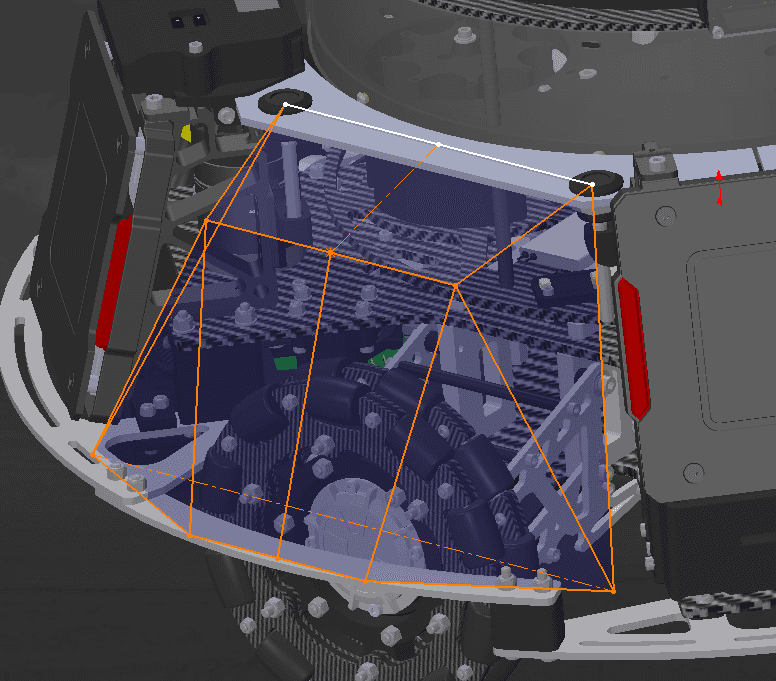


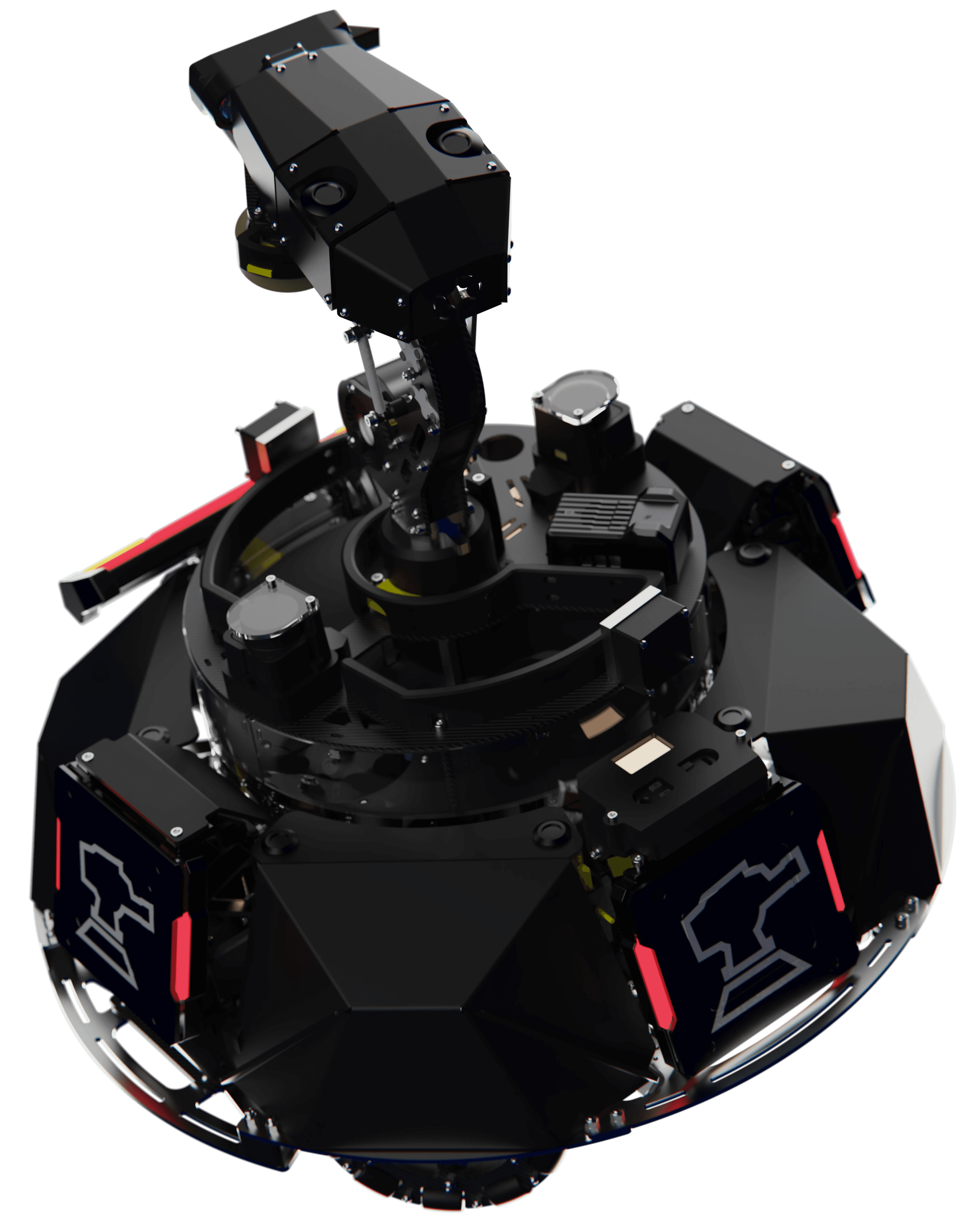
After the form was selected, I used the Sheet Metal workspace to produce a net and then cut and bend the covers into shape. The result: symmetrical, interchangeable covers that look balanced when the robot is spinning and poised when the robot is still.
After the form was selected, I used the Sheet Metal workspace to produce a net and then cut and bend the covers into shape. The result: symmetrical, interchangeable covers that look balanced when the robot is spinning and poised when the robot is still.
Assembly
Proper assembly and wiring of our robot requires thorough understanding of the machine itself and how it is programmed. I created a robust and easily readable wiring diagram for our robot in Figma for quick diagnosis and familiarization at a glance. Wiring itself was an issue until the very end- everyone was simply too tired to label wires all the time, and every time that happened it did not end well.
Proper assembly and wiring of our robot requires thorough understanding of the machine itself and how it is programmed. I created a robust and easily readable wiring diagram for our robot in Figma for quick diagnosis and familiarization at a glance. Wiring itself was an issue until the very end- everyone was simply too tired to label wires all the time, and every time that happened it did not end well.
ROBOT TOUR
ROBOT TOUR
Subsystems
My Contributions
Quick Demo Video
Turret Minor:
The firing system of the robot. Flywheels fire the 17mm ammunition at 25 m/s at 30 hz. Primary visual and depth camera (Intel RealSense) mounting point.
I updated Minor’s armored covers from the legacy edition to improve access and visibility of electronics. Manufacturing the RealSense mount.
Turret Major:
The nervous core of the robot, containing the bulk of onboard processing, including the Nvidia Jetson Orin AGX used for running the AI targeting model. Additionally contains the ammunition magazine and serves as a sensor platform for the auxiliary cameras and LiDAR.
I designed hardware mounting, packaging electronics to minimize dead space through the system while retaining accessibility and reducing EMF.
Yaw Mech:
My personal subsystem. The core subsystem of the robot that serves as both the key connector between the upper and lower robot systems and the yaw mechanism. Backlash optimized to improve odometry characteristics. An absolute through bore encoder paired with a redundant on-axis encoder deliver reliable telemetry. Custom clamping hardware is unyielding in every condition to deliver consistent results under competition load.
Chassis:
Primary drive base and power supply of the robot. X-Drive allows for high-speed translation in any direction while suspension is designed to survive jumps and hard terrain.
Fully designed chassis layout, as well as developing protective battery housing and removable armor covers for internal access without compromising combat effectiveness.

Turret Minor:
The firing system of the robot. Flywheels fire the 17mm ammunition at 25 m/s at 30 hz. Primary visual and depth camera (Intel RealSense) mounting point.
I updated Minor’s armored covers from the legacy edition to improve access and visibility of electronics. Manufacturing the RealSense mount.
Turret Major:
The nervous core of the robot, containing the bulk of onboard processing, including the Nvidia Jetson Orin AGX used for running the AI targeting model. Additionally contains the ammunition magazine and serves as a sensor platform for the auxiliary cameras and LiDAR.
I designed hardware mounting, packaging electronics to minimize dead space through the system while retaining accessibility and reducing EMF.
Yaw Mech:
My personal subsystem. The core subsystem of the robot that serves as both the key connector between the upper and lower robot systems and the yaw mechanism. Backlash optimized to improve odometry characteristics. An absolute through bore encoder paired with a redundant on-axis encoder deliver reliable telemetry. Custom clamping hardware is unyielding in every condition to deliver consistent results under competition load.
Chassis:
Primary drive base and power supply of the robot. X-Drive allows for high-speed translation in any direction while suspension is designed to survive jumps and hard terrain.
Fully designed chassis layout, as well as developing protective battery housing and removable armor covers for internal access without compromising combat effectiveness.

Here is a quick demo video we filmed soon after the robot was done with assembly to test out various of the essential functions such as moving, shooting, and the AI targeting function. Unfortunately not depicted is obstacle avoidance using LiDAR.
Improvements Over 2025 Iteration
Cheaper. Lighter. Smaller. Faster. Stiffer. Deadlier. Through meticulous optimization and integrated design, Achlys improves upon its predecessor significantly- an evolution designed to remain relevant.
RESULTS
RESULTS
Improvements over Previous Iterations
Competition
The Future of the Sentry

Improvements Over 2025 Iteration
Cheaper. Lighter. Smaller. Faster. Stiffer. Deadlier. Through meticulous optimization and integrated design, Achlys improves upon its predecessor significantly- an evolution designed to remain relevant.


Cost
$9000
$15,000
60%
Weight
19kg
24kg
79%
Firing System Intertia
0.007kgm^2
0.02kg*m^2
35%
Translational Speed
1.5 m/s
167%
2.5 m/s
Magazine Efficiency size/magazine capacity
0.78
109%
0.85
Max Firing Speed
29hz
144%
42hz
'Eclipse'
2025
'Achlys'
2026
Competition
Over-complicated designs and delayed timelines have always plagued Sentry. This year, it was different!
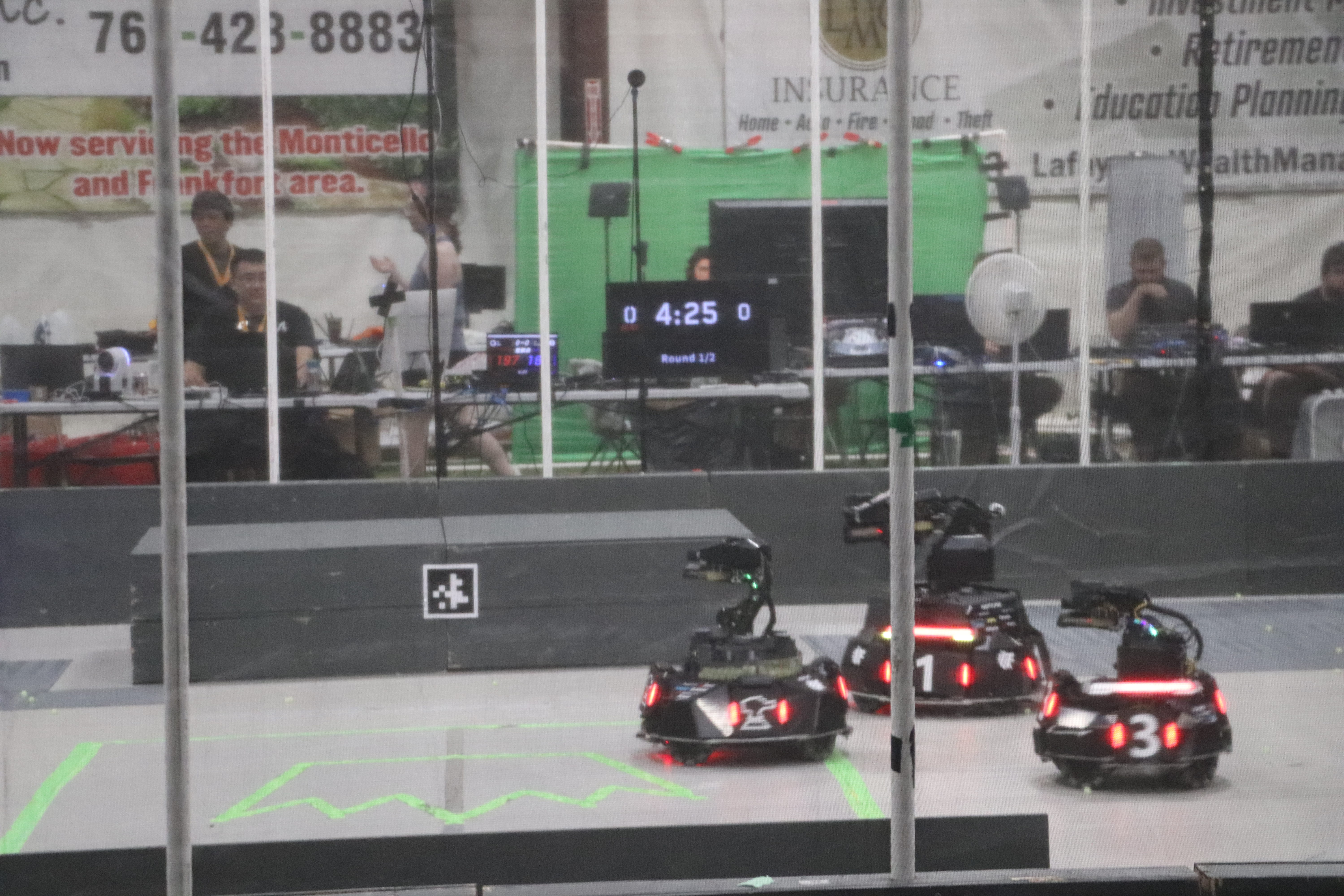
Although in the first couple of matches, software was still fixing bugs, in the later matches we got to see Achlys's potential. In one match, it ripped almost 90% of an opposing Sentry's health in seconds (I was astonished seeing a robot lose health that fast) , turning the tide of a match.
Mechanically, it survived all punishment without complaint and all components remain aligned and intact where other robots failed.
In the end, we walked away from competition satisfied. Mechanically, this platform is ready for the future. After years of work, we finally have an architecture that works. Our problem to solve next year is consistency. Software needs more time.
Competition
Over-complicated designs and delayed timelines have always plagued Sentry. This year, it was different!
Although in the first couple of matches, software was still
… See More



Improvements for Next Year
New Sensors
The largest issue that Achlys had to deal with was unreliable localization. Although the LiDAR obstacle avoidance prevented it from damaging itself, our assumption that the visual fiducial markers were sufficiant for localization were incorrect, confusing the robot and causing it to behave unpredicatbly. This year, we will be running a more robust 3-D LiDAR using a SLAM algorithm for localization.
Composite Layup Armor
A personal project- instead of using bent ABS for armor paneling, I want to experiment with doing more advanced carbon fiber layups- not just making sheets in the platen press but actual 3D geometry that I will have to design a mold for. Due to a generous donation by our carbon sponsor TORAY, this wild idea might yet come to fruition.
Improvements for Next Year
New Sensors & Composite Armor
The largest issue that Achlys had to deal with was unreliable localization. Although the LiDAR obstacle avoidance prevented it from damaging itself, our assumption that the
… See More
